Peer-to-peer communication was classified into seven tiers by the International Organization for Standardization in 1978. There are two sets of these layers. When a user sends or receives a message, the upper four layers are utilized. Host computers employ the lower three tiers of the OS stack whenever a message is transmitted. Each layer performs a specified task or activity to complete the communication. Each of the seven layers has a specific role.
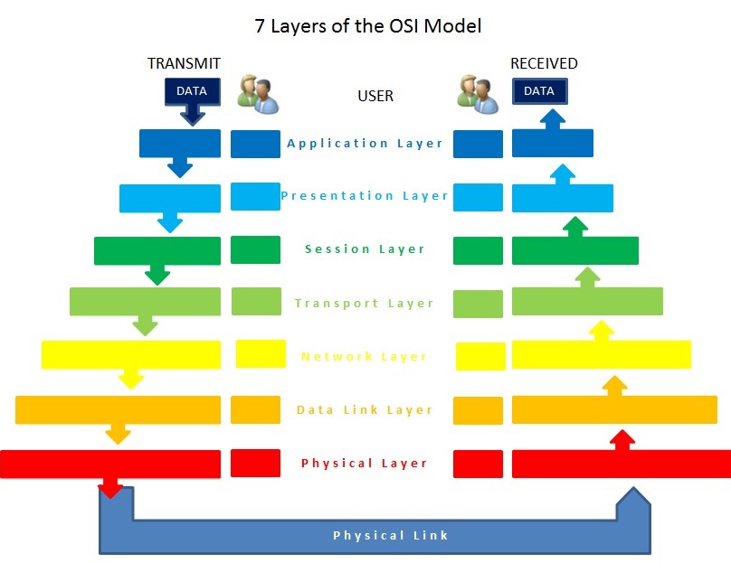
Upper Layers
Upper layers are more focused on the application than the lower levels, which are focused on transporting packets to their final destinations.
Layer 7 – Application
The application layer is the seventh layer of the OSI model, the layer communicates directly with the end-user during the application-layer process. Protocols such as SMTP, DHCP Telnet, POP3, HTTPS, HTTP, and others focused on process-to-process communication through an IP network (internet) are included in this layer (Kumar, Dalal & Dixit, 2014). This layer also includes an end-user service interface and a business communication interface. Application-layer hardware includes things like gateways, proxy servers, application switches, and content management firewalls. This layer provides support for various applications and services, including transferring files, web browsing, emailing clients, database access, and network games.
Layer 6 – Presentation
The presentation layer, which is typically included in an operating system, is responsible for formatting the data shown to the application layer. The data is converted from one presentation format to another when it comes in and out of the computer. This layer is supported by protocols such as TSL, SSL, and MIME. In addition to compression and encryption, the job of this layer is to ensure that the character code set (ASCII, UNICODE, EBCDIC, and so on) could be decoded on either side. Gateways, as well as redirectors, are examples of hardware that is found at the presentation layer.
Layer 5 – Session
In computer networking, the session layer is in charge of originating, maintaining, as well as terminating connections among programs on either end of a channel of communication. This layer uses the SIP (Session Initiation Protocol) and RTP (Real-time Transport Protocol) protocols, respectively. A set of functionalities enables programs to communicate over a network while also conducting logging, name recognition, and security, among other things.
Layer 4 – Transport
The transport layer is responsible for ensuring that information is delivered error-free, and in order, as well as making sure it does not have any duplication or loss. This layer is accountable for dividing the data into smaller packets to ensure that the missing packets will be delivered again if any packets are lost during transmission. The transport layer at the receiving host has the responsibility of opening all of the packets and reassembling the original message. Sequencing of TCP (Transmission Control Protocol) sections is another feature of this layer. Sequencing corrects TCP segments that have been transmitted out of sequence. UDP is another transport-layer protocol (User Datagram Protocol). De-multiplexing and multiplexing through “Port Number” are made possible with the help of UDP and TCP.
Lower Layers
Sending and receiving packets are handled by the lower layers of the network.
Layer 3 – Network
The network layer decides which physical path the data must follow depending on the network conditions, priority, and other considerations. The OSI model’s foundation rests on this layer. This network layer handles IP addresses, typically related to RARP, IPsec, ICMP, IGMP, and other protocols. Switches, firewalls, routers, and other network-layer computer gear are the most popular.
Layer 2 – Data Link
The data link layer is the most complicated of the three layers. It ensures that the communicated data is legitimate from beginning to end at the end of the transmission chain. The data link layer is responsible for encapsulating raw bits from the physical layer into frames. Technically, this layer can be broken down into two different layers: the Logical Link Control (LLC) sublayer as well as the Media Access Control (MAC) sublayer. The Network Address Conversion sublayer calculates the physical addresses of the hosts and enables the data link layer to provide the best transmission medium. In contrast, the LLC sublayer is in charge of data flow, error checking, and synchronizing the network throughout the network. Wireless access points and network interface cards (NICs) are data link layer hardware that uses standards and protocols such as SLIP, PPTP, PPP, and L2TP.
Layer 1 – Physical
This layer of the OSI model is involved with the transfer of bits from one system to another as well as the regulation of the transmission of a stream of bits over a physical medium. It is the bottom layer of the model and is focused on the transfer of bits from one system to another (Zhao et al., 2018). It is responsible for describing the electrical/optical, mechanical, and function connections to the physical media and carrying signals for all of the higher levels of the architecture. The software also handles the transmission rate, which helps to enhance the flow of data between a receiver and a sender. There are only a few standards as well as protocols used by this layer, including 802.11 (Wi-Fi), 802.5 (Token Ring), and IEEE 802.3 (Ethernet). Ethernet cards, CAN, Bluetooth, USB, ISDN, and DSL are examples of hardware used by the physical layer of the OSI model of computing.